|
This article was originally written in 1996 & 1997 when these parts were still provided by Pioneer. This approach to adding Dolby Digital is only valid now by cannibalizing old players.
Warning!
The information provided here is not provided or approved by Pioneer Electronics. No liability for damages to players and/or parts will be assumed by the author. Proceed AT YOUR OWN RISK.
Background
Pioneer introduced Dolby Digital (AC-3) to the home theater world in November 1994. The technology used to provide 5.1 audio to theaters would now be available in the home via LaserDisc. This would be the first home use of discrete channel film soundtracks. The signal incorporated into LaserDisc would occupy the bandwidth originally used for the Right Analog (FM) channel, leaving the PCM channels for the typical Dolby Pro-Logic Surround track, and the Left Analog audio track for a mono film soundtrack or other audio program (commentary, isolated score, etc). The competing 5.1 surround system was DTS Digital Surround, which replaced the entire PCM track with their data stream, leaving both analog audio tracks for either Dolby Pro-Logic sound, or other programming. While both required specific players, any LaserDisc player with a Digital Audio output (Optical or Coaxial) could play a DTS soundtrack (through a properly equipped receiver/decoder), while Dolby Digital not only required a new player (with the AC-3 output), but a new receiver with the AC-3 RF input. Arguments over which format was truly "backward compatible" raged on ... well forever.
Research
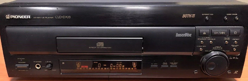 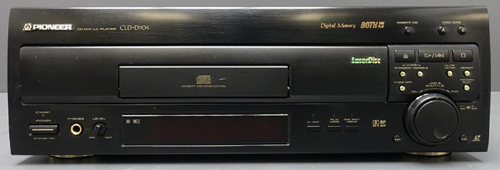 The picture on the top left is the CLD-D703 with the CLD-D704 below. From the front, they are nearly identical. In fact, the only difference is the "AC-3 RF OUT"
logo under the drawer. When Pioneer introduced the CLD-D704, I had purchased the D703 only a few months previous. Not wanting to spend the cash to swap out players that appeared practically identical, I began exploring options to upgrade my current player. I started out by purchasing the service manuals for both players and looking at the board layouts for where the AC-3 plug was added. The AUDB board is responsible for all audio processing in both players. After verifying the boards were nearly identical, it occurred to me that simply dropping the board from a CLD-D704 into the CLD-D703 and drilling the required hole in the back panel was all I needed.
The picture on the top left is the CLD-D703 with the CLD-D704 below. From the front, they are nearly identical. In fact, the only difference is the "AC-3 RF OUT"
logo under the drawer. When Pioneer introduced the CLD-D704, I had purchased the D703 only a few months previous. Not wanting to spend the cash to swap out players that appeared practically identical, I began exploring options to upgrade my current player. I started out by purchasing the service manuals for both players and looking at the board layouts for where the AC-3 plug was added. The AUDB board is responsible for all audio processing in both players. After verifying the boards were nearly identical, it occurred to me that simply dropping the board from a CLD-D704 into the CLD-D703 and drilling the required hole in the back panel was all I needed.
Of couse, this did present a small problem. The RF signal feeding the AC-3 section (labeled SRD on the board) is not sourced from the same place the RF signal is presented for the rest of the audio. In fact, the plug for the "legacy" signal is at the other end of the board! Rather than change the layout of the board (and increase costs), Pioneer added a new connector to the AUDB board to receive the raw RF signal from the VSOP (main system board). To provide this new signal, they made a small alteration to the VSOP and added a connector for the RF signal to jumper up to the AUDB. The result is the exact same RF signal is provided to the AUDB board in two places. I guess making a minor tweak to two boards costs less than making a large modification on one. Not wanting to incur the expense of replacing the VOSP board as well, we'll have to find another way to get the AC-3 connector the required signal. My plan was clear (in my mind), but exactly HOW to pull it off was still undetermined.
Upgrade
I purchased the AUDB Assembly (P/N: VWV1419) from Pioneer Electronics Service for $160. Making a jumper from the existing RF input to the board (CN204, Pins 6 & 7) to the new CN123 connector for the AC-3 section seemed like the most reasonable step. The AUDB board comes with a jumper to feed the headphone jack on the front panel. I cut a section of wire off this connector and made my connections.
 This is an enlarged section of the AC-3 section of the AUDB board for CN123 and CN204, to show the connectors involved in this modification. The connectors are in blue with the new jumper in green. Note that on CN204, the RF is on Pin 6 with GND on Pin 7 and on CN123,
the GND comes first on Pin 1 with SRD (RF) on Pin 2. Pay attention to your polarity. Proper polarity is very important. Carefully solder your jumper in place. Don't overheat the components. Now we're ready to mount the new AUDB board into the CLD-D703 player...almost.
This is an enlarged section of the AC-3 section of the AUDB board for CN123 and CN204, to show the connectors involved in this modification. The connectors are in blue with the new jumper in green. Note that on CN204, the RF is on Pin 6 with GND on Pin 7 and on CN123,
the GND comes first on Pin 1 with SRD (RF) on Pin 2. Pay attention to your polarity. Proper polarity is very important. Carefully solder your jumper in place. Don't overheat the components. Now we're ready to mount the new AUDB board into the CLD-D703 player...almost.
To make room for the new connector, you will need to drill a hole into the back plate. You'll want to relocate the serial number sticker to another location. Drill a 7/16" hole approximately 5/8" from the top of the back panel and 2" to the left of the of the existing RCA connectors.
Exact spacing of the connectors can be done prior to mounting the AUDB board into the player. Double-check your measurements before drilling. There is also a screw-down anchor hole on the connector.
Once all of the holes have been drilled and board is installed, it's time to hook everything up. The diagram on the right is a modified graphic extracted from the CLD-D703 operations manual. I have added the Dolby Digital connector as well as connections at the amplifier end for Dolby Digital and DTS Digital Surround.
This same approach can be used to upgrade the Pioneer CLD-07G LaserDisc player as well. There is one additional modification that must be made to the AUDB board because of an additional piggyback board that player uses for LaserDisc Graphics. There is a large capacitor on the AUDB board that needs to be reoriented so the daughter board will sit properly. If you're handy with a soldering iron, it's a piece of cake.
Conclusion
These modifications allow this player to be used with literally any of the LaserDiscs ever made (ok, not EVERY; no PAL playback). This is not a viable upgrade path for most players, but I have used it to upgrade the Japanese CLD-07G player as well, so I've got LD-G playback too!
|